
3 Wire Strobe Light Wiring Diagram Wiring Diagram
In the mesmerizing world of automotive modifications, strobe lights have stolen the spotlight. But understanding the intricacies of their wiring can be overwhelming. Fear not, as we unveil the mystical realm of the 12v 3 wire strobe light wiring diagram. With a dash of creativity, we'll demystify the process, shedding light on how these mesmerizing beacons come to life!

3 Wire Strobe Light Wiring Diagram
Without an Existing Alarm Panel. Without an existing alarm panel, use a 12V DC power adapter to power the Konnected device, then we can draw power from the Konnected board to also power the siren. Connect the negative or ground wire leading to the siren to a GND pin on the bottom left of the Konnected board (near the power adapter plug and U1 pins).. Make the following connections to the relay:

3 Wire Strobe Light Wiring Diagram
The explanation of the circuit is given below. Circuit Explanation: The heart of the strobe light circuit is the 555 Timer which is operating in Monostable mode. The 555 Timer can operate in 3 different modes such as Astable, Monostable and Bistable mode.

12v 3 Wire Strobe Light Wiring Diagram Wiring Draw And Schematic
For 12 volt applications, the total number of strobes must not exceed 12, with a maximum loop resistance of 30 ohms. For 4-Wire installations, terminals 1, 2, and 3 connect to the strobe; ter-minals 4 and 5 connect to the horn. The horn and strobe circuits must be wired independently, and each circuit must be terminated with the appro-
4 Wire Strobe Light Wiring Diagram Wiring Diagram
IV. WIRING Wiring for synchronized strobes and horns. Using this method you may: w Use only two wires to synchronize the temporal horn and strobe with the ability to mute the horn (place switches 1and 2in the ON position on the GEC3-12). w Mute the horn only when the temporal horn option has been selected. w Use the Gentex synchronization protocol to provide synchronization and mute the horn.

12v 3 Wire Strobe Light Wiring Diagram Wiring Draw And Schematic
positive wire after 2.5 seconds, then all the lamp will back to the first flash pattern. Then all the lamp will be synced. 3. Connect the positive (Red) wire of the power and the sync wire after 0.5 seconds, all the lamp will sync with new flash pattern. 4. If the lamps do not sync after a long time, please start at step 2 again. Red: Anode.

6 Way Strobe Light Wiring Diagram
12v 3 Wire Strobe Light Wiring Diagram - Wiring Draw And Schematic

3 Wire Strobe Light Wiring Diagram Wiring Draw And Schematic
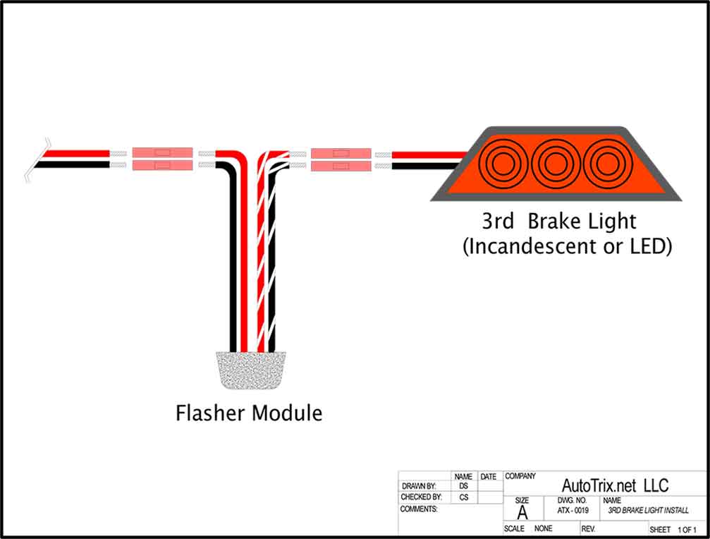
2. Using a 1/4" drill bit, drill the four mounting holes and install the four supplied fastex screw grommets into the holes. Install a grommet (customer supplied) into the 1" wire hole to protect the wires. 3. Using appropriately sized wires (minimum wire size / 18 AWG), extend the wires to their connections (See "Wire Designations").
3 Wire Led Light Wiring Diagram / I Want To Repair An Led Christmas
Push the defective strobe tube assembly out of the reflector. Disconnect the red 3-position connector at the end of the tube's wiring. To facilitate assembly, apply a high temperature grease, or Vaseline, to the rubber edge of the strobe tube. SLOWLY insert the strobe tube into the reflector housing.

3 Wire Strobe Light Wiring Diagram Wiring Draw And Schematic
INSTALLATION SCHEMATIC / WIRING DIAGRAM 4. CONTROL & POWER INPUT's:. strobe (@12V): 0.65 A (3.2 A peak) Ambient temperature: from -55°C to +85°C / from -67°F to +185°F. c. Yellow wire Strobe light function wire (positive lead) d. Blue wire Use if the synchronization of the Aveo lights is selected 3. Testing of the function of the.

[DIAGRAM] Whelen Strobe Wiring Diagram Connector
Phone: (860) 526-9504. Sales Email:[email protected]. Canadian Sales:[email protected]. Customer Service:[email protected]. M4 Series LED Lighthead: 2- & 5-wire (12-Volt) Safety First: This document provides all the necessary information to allow your Whelen product to be properly and safely installed.

5 Wire Led Strobe Light Wiring Diagram
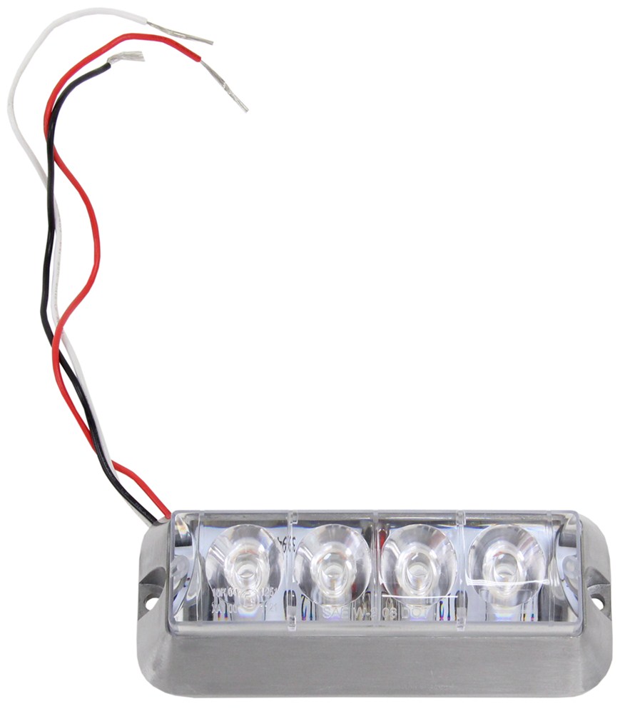
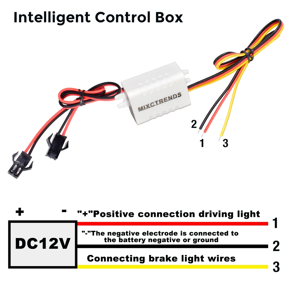
A 3 wire strobe light is composed of three different wires: power, ground, and strobe. The power wire supplies power to the device, while the ground wire is a safety measure that prevents electric shock. The strobe wire is responsible for controlling the flashing frequency of the strobe light.
Whip Light Wiring Diagram
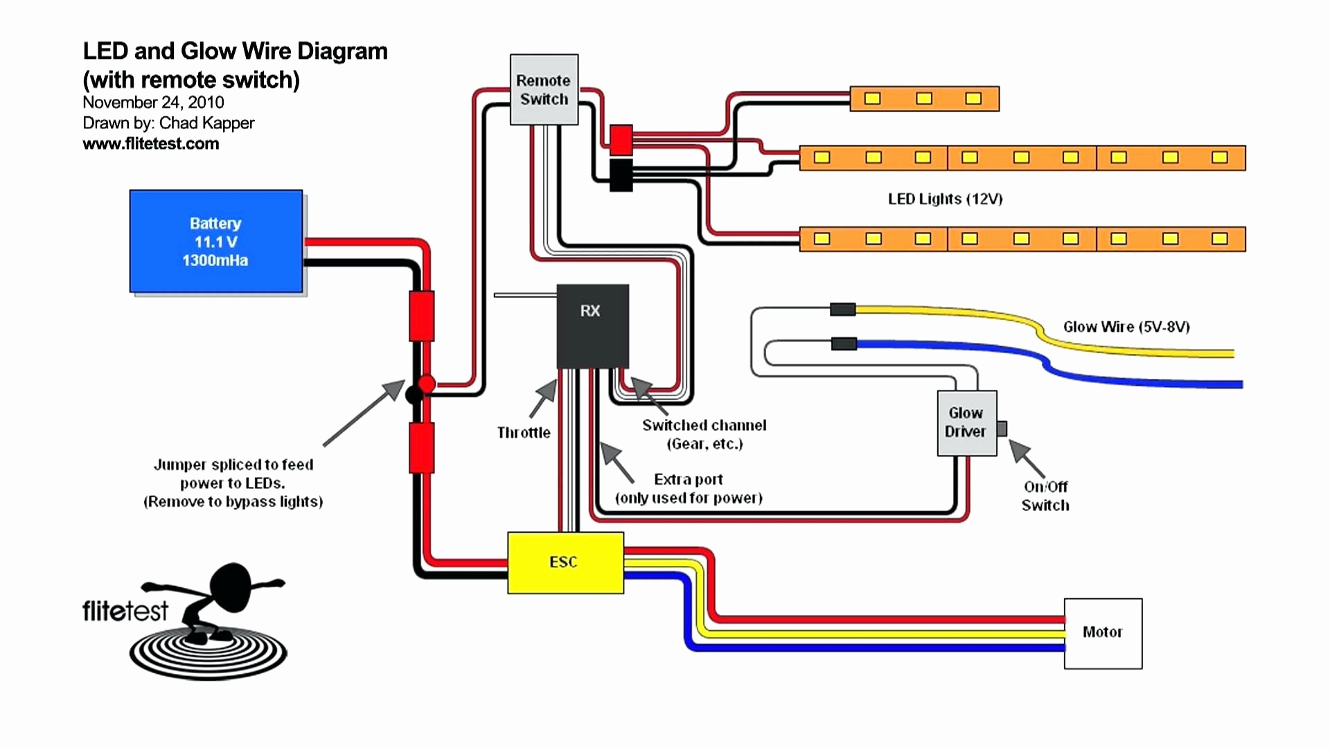
There are three essential elements: the power source, the relay switch, and the strobe light. The power source is typically a 12V battery, although it can also be connected to a mains outlet. The relay switch is responsible for controlling the on/off cycle of the strobe light, while the strobe light itself is responsible for emitting the bright.
Strobe Wiring Diagram uAvionix
The great thing about strobe lights is that they can be used with most wiring systems, meaning that all you need to do is understand the basics of 12v strobe light wiring diagram and you'll be off and running in no time. Starting out with a 12v strobe light wiring diagram is easy, but it helps to understand the different components involved.
32 Strobe Light Wiring Diagram Wiring Diagram Niche
red wire connects to positive and the black wire connects to negative. If the connections are reversed, the light will not function. Use 18-gauge wire for runs under 20-feet. For wire runs over 20-feet, consult local electrical codes. Ensure that the vehicle's supply voltage is within the voltage rating specified on the strobe light.
tektone wiring diagrams
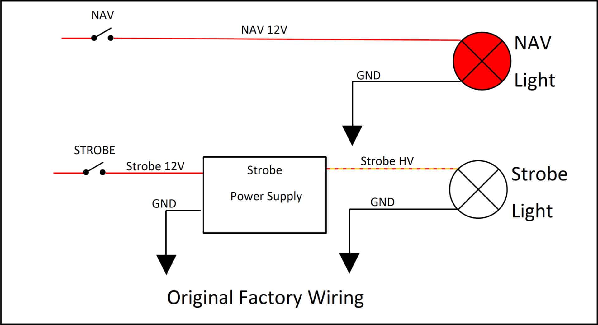
A 3 wire strobe light wiring diagram is designed to outline 3 different phases of power required for your lighting fixtures to function properly. These 3 wires enable you to create the necessary circuits to make your lights work. Let's discuss each one in more detail. What Does A 3 Wire Strobe Light Wiring Diagram Show?
